
Why Ship Ballast Piping Leaks at Joints and How Maintenance Teams Can Stop It
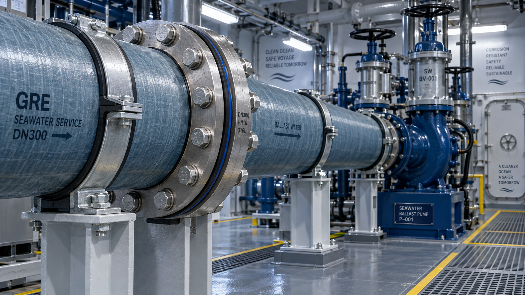
A joint leak in a ballast line rarely begins as a dramatic failure. More often, it appears during a routine tank transfer, after a pump starts, or when a vessel returns to service following maintenance. A damp flange edge, white salt deposits, a drop in pressure stability, or repeated tightening of the same bolts can all signal that the joint is losing integrity. Left unresolved, the leak can accelerate corrosion around supports and adjacent steelwork, contaminate compartments, interrupt ballast operations, and turn a small repair into an urgent docking task.
The practical answer is to treat a leaking joint as a system condition rather than simply a loose-bolt problem. Most Ship Ballast Piping joint leaks result from one or more of five causes: poor flange alignment, incorrect gasket selection or compression, damaged sealing faces, movement caused by vibration or inadequate support, and pressure or temperature cycling that gradually relaxes the joint. Stopping repeat leaks requires identifying which of these conditions is present before the joint is reassembled.
Start with the leak pattern, not the wrench
Before loosening a flange or replacing a gasket, record when and where the leakage occurs. A joint that leaks only while the ballast pump is running points to a different problem than one that weeps continuously at rest. Intermittent leakage may be associated with pressure surges, pipe movement, vibration, or a valve operating sequence. Constant seepage is more likely to involve gasket damage, uneven compression, flange-face defects, or contamination trapped in the sealing area.
The location of moisture also matters. Water appearing evenly around the flange perimeter often suggests insufficient or uneven gasket compression. Leakage concentrated near one bolt position can indicate a local flange distortion, a damaged bolt, an alignment issue, or a foreign particle on the sealing face. Water tracking from above the joint may not originate at the flange at all; inspect nearby valves, vent lines, pipe penetrations, and overhead joints before concluding that the visible flange is the source.
For ballast systems, do not overlook the effect of seawater residue. Crystallized salt can make an old leak appear active, while a freshly washed joint can conceal a slow seep. Clean and dry the area, then observe it through the relevant operating condition. Where permitted by vessel procedures, a controlled pressure hold after cleaning provides a more reliable indication than judging the joint from stains alone.
Why joints in ballast lines lose their seal
Flanges forced into position during installation
A pipe spool should meet its mating flange without being pulled into place by bolts. When bolts are used to close a gap, correct angular mismatch, or overcome lateral offset, the flange faces can be loaded unevenly. The gasket may initially seal, but the stored stress remains in the pipework. As the system vibrates, sees pressure changes, or shifts slightly on its supports, that stress is released through the joint.
This issue is especially important after replacement work. A newly fabricated spool may have the correct nominal dimensions yet still be difficult to fit because supports have moved, hull structure has flexed, or neighboring pipe sections are carrying load. Repeated bolt tightening cannot correct a misaligned assembly. It often damages the gasket and may distort the flange face further.
Gaskets that do not suit the service or joint design
Not every gasket that fits the flange is suitable for ballast service. The material must be compatible with seawater or treated ballast water, the expected pressure range, flange-face configuration, and the bolt load available at the joint. A gasket that is too soft can extrude or creep under load. One that is too hard may not conform to minor surface irregularities. A gasket with the wrong inside diameter can intrude into the flow path or be difficult to center, while an oversized gasket can leave too little supported sealing area.
Reusing a compressed gasket is another frequent source of recurring leakage. Once removed, the gasket may have permanent deformation, torn edges, embedded debris, or altered thickness. It may look usable but no longer provide uniform recovery when the flange is retightened. A removed gasket should normally be replaced rather than turned over and installed again.
Uneven bolt loading
Bolts do not merely hold two flanges together; they create the controlled compression that allows the gasket to seal. Random tightening, tightening one side fully before the opposite side, or relying on “feel” for critical joints can create high load at a few bolts and low load elsewhere. The gasket then compresses unevenly, leaving a path for water at its least-loaded section.
Corroded threads, damaged nuts, mixed fasteners, and inadequate lubrication can also produce misleading torque. Two bolts tightened to the same torque may deliver very different clamping loads if one has rough threads or heavy corrosion. During planned maintenance, inspect fasteners as part of the joint, not as separate hardware. Replace fasteners that are stretched, deeply corroded, damaged, or unsuitable for the flange assembly.
Sealing faces damaged by previous repairs
Flange faces are often harmed during gasket removal. Scrapers, chisels, grinding discs, and aggressive wire brushes can leave scratches across the sealing path. Deep radial marks are particularly problematic because they can form channels from the bore toward the outer edge. Paint overspray, cured sealant residue, corrosion scale, and loose fibers can have a similar effect by preventing full gasket contact.
Inspect the sealing surface under good light after the gasket is removed. Look for pitting, raised burrs, gouges, cracks, flange rotation, and uneven surface condition. Minor residue can be cleaned using a method suitable for the flange material. Do not assume that heavy grinding is a repair; removing material without controlling flatness or surface finish can make a leaking joint worse.
Movement from vibration, support problems, and pressure cycling
Ballast pumps, valve operation, flow changes, and vessel motion all place loads on piping. A flange near a pump discharge, a branch connection, or an unsupported spool may experience repeated movement. Even a well-assembled joint can gradually lose sealing margin when the pipe is bending, twisting, or vibrating against the flange.
Pressure cycling can have the same effect. Rapid pump starts, abrupt valve closures, blocked vents, or unstable control sequences can produce transient loads beyond normal steady operation. When a joint leaks after a particular operating event, inspect the operating sequence as well as the flange. Replacing a gasket without addressing the pressure event may only postpone the next failure.
A practical inspection sequence before repair
Isolate, drain, depressurize, and make the section safe according to the vessel’s procedures before opening the joint. Confirm that there is no trapped pressure, backflow path, or tank condition that could refill the line. Once access is safe, use the inspection to determine whether the repair should be limited to the joint or expanded to supports, adjacent spools, or operating controls.
- Confirm the leak source. Clean the external area and inspect nearby connections. Trace the first point where moisture emerges rather than following the path water has taken across the pipe surface.
- Check the joint externally. Look for uneven flange gaps, missing or mismatched bolts, corrosion around bolt holes, cracked backing rings, displaced gaskets, or contact between the pipe and surrounding structure.
- Assess support condition. Inspect hangers, clamps, guides, and brackets on both sides of the joint. A loose clamp, seized sliding support, or missing guide can transfer pipe load directly into the flange.
- Open the joint carefully. Note whether the gasket is crushed more on one side, torn near a bolt, displaced inward, or visibly contaminated. These observations often reveal the original failure mechanism.
- Inspect faces and alignment. With the gasket removed, examine flatness, surface damage, and whether the two faces meet naturally. Do not use bolts to pull a visibly offset flange into alignment.
- Review the operating history. Ask whether the leak followed pump maintenance, valve changes, tank cleaning, pressure testing, a pipe replacement, or unusual vibration. Timing can narrow the cause quickly.
For composite piping systems, inspection should also include the flange construction itself. Cracking, delamination, damage around bolt holes, or softening caused by incompatible materials requires a different response from ordinary metallic-flange corrosion. The repair method, gasket type, bolt loading, and allowable surface preparation should match the piping manufacturer’s joint instructions.
Reassemble the joint so the gasket can do its job
A reliable repair begins with clean, undamaged faces and a new, correctly specified gasket. Keep the gasket dry and free from oil, grit, old sealant, and loose corrosion particles. Do not apply jointing compound unless it is specifically approved for the gasket and flange arrangement. Excess sealant can interfere with compression, migrate into the line, or conceal surface damage that should be corrected.
Bring the flanges together without side loading. The faces should be parallel and centered before tightening begins. Install bolts and nuts in the correct orientation for access and inspection, then tighten them in a staged cross-pattern. The purpose of the pattern is to distribute compression gradually around the gasket rather than crush one area first. Several passes are normally needed, increasing load progressively until the specified final value is reached.
Use the torque or tightening method specified for the joint design. A generic value is not dependable because bolt size, lubrication condition, flange material, gasket type, and pressure class all influence the required load. This is particularly important for GRE systems, where excessive bolt load can damage flange components while insufficient load allows leakage. The technical considerations behind composite ballast lines are discussed in The application of GRE piping in marine ballast water systems.
After tightening, inspect the flange gap around its circumference. An uneven gap may indicate that the gasket has shifted, the faces are not parallel, or the assembly remains under pipe strain. Correct this before pressure testing. A test that passes briefly while the pipework is restrained in an abnormal position may not remain leak-free during normal vessel operation.
When retightening helps—and when it hides the real fault
Retightening can be appropriate only in controlled circumstances: the joint is known to be correctly assembled, the leak is slight, the flange faces are undamaged, the gasket remains suitable, and the piping is not misaligned or moving excessively. It should be performed under the approved procedure, using an even cross-pattern rather than tightening only the bolt closest to the leak.
Retightening is not a cure for a damaged gasket, a warped flange, persistent pipe strain, or an incorrectly selected sealing material. It may temporarily reduce leakage while concentrating more stress into the weakest part of the assembly. In composite flanges, indiscriminate extra tightening can create damage that is not obvious until the next pressure cycle.
A useful rule is that a joint leaking soon after correct reassembly should be investigated, not repeatedly tightened. Repeated interventions at the same location indicate that something beyond routine gasket relaxation is acting on the joint.
Preventing the next ballast piping joint failure
Preventive work is most effective when it focuses on the conditions that cause the joint to change after installation. During routine rounds, inspect areas near pump connections, valves, bends, bulkhead penetrations, and pipe supports. These locations are more likely to see movement or concentrated stress. Watch for salt tracks, corrosion around fasteners, polished marks where piping contacts structure, missing support hardware, and recurring moisture after operation.
Maintenance records should identify the joint location, gasket type, observed condition, repair method, and operating circumstances. This is not paperwork for its own sake. When the same flange leaks after different repairs, records can show whether failures follow a pump start, a particular tank sequence, repeated vibration, or a recurring alignment issue after nearby work.
Spare gaskets and fasteners should be controlled by specification rather than appearance. Keeping several similar-looking gasket materials in stores without clear identification increases the chance of installing an unsuitable item during an urgent repair. Protect gasket stock from moisture, distortion, contamination, and excessive heat, since poor storage can affect sealing performance before installation.
Where a ballast line is being modified or renewed, evaluate the joint arrangement along with the pipe material. Composite systems can reduce corrosion concerns in seawater service, but their connection details must be installed and maintained according to their design limits. Review the piping supports, flange type, gasket requirements, bolt-loading procedure, and adjacent equipment movement as one assembly. That approach is far more likely to eliminate repeat joint leaks than replacing the gasket alone.
Questions that often arise during leak repairs
Can a flange leak because the bolts are too tight?
Yes. Excessive or uneven tightening can crush or damage a gasket, distort a flange, and concentrate load near selected bolts. This is a particular concern where flange materials have lower tolerance for overloading than steel. Tightening must follow the specified sequence and load range.
Should a leaking ballast flange be repaired with sealant applied around the outside?
External sealant may obscure the source and is not a substitute for restoring the internal gasket seal. It can be considered only where an approved temporary procedure specifically permits it. A persistent leak should be repaired by addressing alignment, face condition, gasket selection, bolt load, and pipe movement.
Why does a joint pass a static test but leak in service?
A static test may not reproduce pump vibration, pressure transients, pipe movement, or the temperature and load changes present during operation. Inspect supports and operating conditions when a joint passes at rest but leaks during ballast transfer.
Please give us a message
产品介绍产品介绍产品介绍产品介绍产品介绍产品介绍产品介绍产品介绍产品介绍产品介绍产品介绍产品介绍产品介绍产品介绍产品介绍产品介绍产品介绍产品介绍产品介绍产品介绍产品介绍产品介绍产品介绍产品介绍产品介绍产品介绍产品介绍产品介绍产品介绍产品介绍
Please give us a message
产品介绍产品介绍产品介绍产品介绍产品介绍产品介绍产品介绍产品介绍产品介绍产品介绍产品介绍产品介绍产品介绍产品介绍产品介绍产品介绍产品介绍产品介绍产品介绍产品介绍产品介绍产品介绍产品介绍产品介绍产品介绍产品介绍产品介绍产品介绍产品介绍产品介绍
Please give us a message
产品介绍产品介绍产品介绍产品介绍产品介绍产品介绍产品介绍产品介绍产品介绍产品介绍产品介绍产品介绍产品介绍产品介绍产品介绍产品介绍产品介绍产品介绍产品介绍产品介绍产品介绍产品介绍产品介绍产品介绍产品介绍产品介绍产品介绍产品介绍产品介绍产品介绍
Please give us a message
产品介绍产品介绍产品介绍产品介绍产品介绍产品介绍产品介绍产品介绍产品介绍产品介绍产品介绍产品介绍产品介绍产品介绍产品介绍产品介绍产品介绍产品介绍产品介绍产品介绍产品介绍产品介绍产品介绍产品介绍产品介绍产品介绍产品介绍产品介绍产品介绍产品介绍