
Handling Fatigue Loading on Topside GRE Pipe Supports: What Design Engineers Must Verify
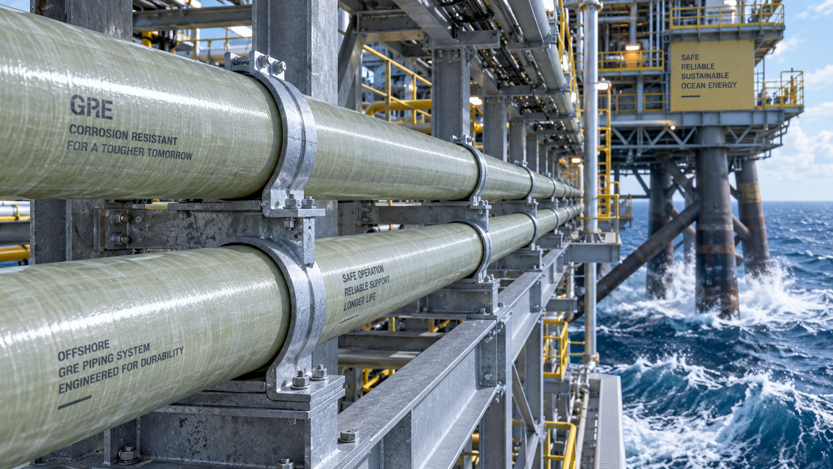
Handling Fatigue Loading on Topside GRE Pipe Supports: What Design Engineers Must Verify
For project managers and engineering leads in offshore oil and gas, selecting GRE pipe for offshore applications brings a critical design responsibility: verifying support systems under fatigue loading. Beyond static strength, cyclic stresses from waves and vibrations demand rigorous analysis. This guide outlines essential checks for topside supports, ensuring long-term integrity and safety.
Why Fatigue Loading Is the Real Threat to GRE Pipe Supports
Offshore topside piping systems face continuous dynamic forces that static design calculations simply do not capture. Wave action, equipment vibration, thermal expansion cycles, and even slug flow create repeated stress reversals that slowly degrade both pipe and support components. For GRE pipe for offshore installations, this degradation mechanism differs fundamentally from steel piping behavior.
Glass reinforced epoxy composites exhibit excellent corrosion resistance and high specific strength, yet their fatigue characteristics are anisotropic and highly dependent on fiber orientation and laminate architecture. A support designed for static weight may fail prematurely under cyclic loading, not because of overstress but because of accumulated micro-damage within the composite matrix. This makes fatigue verification non-negotiable.
Design engineers must understand that fatigue failure in GRE systems typically appears at support contact points, clamp edges, and areas of localized stress concentration. The material does not yield and redistribute stress like ductile steel; it fractures abruptly once fatigue life is exhausted. End users therefore need a verification methodology that accounts for these unique failure modes.
What Load Combinations Should Engineers Evaluate for GRE Pipe for Offshore Platforms
Many design teams make the mistake of analyzing only the most severe single load case. Fatigue verification requires evaluating load pairs and sequences, because damage accumulation depends on stress range rather than peak magnitude alone. The governing fatigue loads on topside GRE supports generally combine vertical dead loads with cyclic lateral forces.
Wave-induced platform motion creates low-frequency, high-amplitude displacements that propagate into the piping system. Meanwhile, high-frequency vibrations from rotating equipment introduce smaller but vastly more numerous stress cycles. Both contributions must enter the fatigue spectrum simultaneously, along with thermal cycling from process temperature variations and pressure pulsations from fluid flow.
Engineers constructing fatigue load cases for GRE pipe support verification should also include hydrodynamic loading from wind and current acting on exposed pipe runs. These environmental loads vary in direction and magnitude, producing multi-axial stress states at support points. Ignoring any load component risks underestimating the true fatigue damage rate.
How to Calculate Fatigue Life of GRE Pipe Supports Accurately
The S-N curve approach remains the industry standard, but applying it to GRE composites demands careful interpretation. Unlike metals, which show a well-defined endurance limit, GRE materials typically display continuous slope in the high-cycle region without a true fatigue limit. This means engineers cannot assume infinite life; every stress cycle consumes a finite portion of material life.
Fatigue life calculation for GRE pipe for offshore applications requires converting global loads into local stresses at critical support locations. FEA modeling should incorporate contact behavior between clamp and pipe surface, friction effects, and the anisotropic stiffness properties of the laminate. Contact pressure distributions under cyclic loads often reveal peak stresses far exceeding nominal values.
Miner's rule remains acceptable for preliminary screening when stress levels remain below the proportional limit. However, more sophisticated cumulative damage models become necessary when load spectra show wide amplitude variation or when mean stress shifts occur between cycles. Engineers should validate analytical results against full-scale fatigue test data whenever project criticality justifies the cost.
Support Spacing and Clamp Design: Where Fatigue Failures Actually Occur
Support spacing directly controls the bending stress range experienced by GRE pipe under dynamic loading. Excessive span increases both static sag and dynamic amplifications at natural frequencies. Conversely, overly close spacing creates multiple constraint points that hinder thermal expansion and induce additional compressive stresses at clamp edges.
Offshore design practice for GRE pipe for offshore topsides typically recommends support spacing of 3 to 5 meters for nominal pipe diameters, but dynamic analysis may require adjustments based on actual vibration modes. Engineers must verify that natural frequencies of pipe spans stay separated from equipment excitation frequencies by a safety margin of at least 20 percent.
Clamp width, liner material, and bolt torque all influence contact stress distribution. Wide clamps reduce peak pressure but increase bending stiffness at the support point. Elastomeric liners distribute load evenly yet may undergo creep or set over years of cyclic service. Regular torque verification during operation becomes as important as initial installation calibration.
What Inspection Intervals Make Sense for GRE Pipe Offshore Support Systems
Design verification alone cannot guarantee fatigue integrity throughout the asset lifecycle. Operating stress levels may deviate from design assumptions, especially after process modifications or equipment changes. A structured inspection program should detect early signs of fatigue damage before catastrophic failure occurs.
Visual inspection remains the first line of defense, focusing on surface whitening, resin crazing, or deformation at support edges. Acoustic emission monitoring offers earlier damage detection because micro-crack growth produces characteristic acoustic signatures during load cycles. Thermography also detects subsurface damage through differential heat generation under cyclic loading.
For high-risk supports on critical lines, strain gauge installation during commissioning provides direct validation of design stress predictions. Comparing measured strains with FEA results at equivalent loading conditions confirms that fatigue calculations used realistic boundary conditions. Discrepancies larger than 15 percent warrant reopening the fatigue assessment before continued service.
How to Migrate from Steel to GRE Pipe for Offshore without Sacrificing Fatigue Integrity
Materials substitution projects often fail because engineers transfer steel-specific support designs without modification. GRE pipe for offshore systems requires lighter support structures due to reduced weight, but stiffer clamps to prevent localized bending. The support spacing, clamp design, and anchorage strategy all require re-evaluation rather than simple replacement.
When converting an existing platform from steel to GRE risers or topside lines, the fatigue analysis should start with actual measured wave data for the installation site rather than generic Gulf of Mexico or North Sea spectra. Site-specific wave scatter diagrams and current profiles provide realistic input distributions for cumulative fatigue damage calculations.
Engineers must also verify that existing structural steel supports have sufficient fatigue life when connected to lighter GRE piping. The reduced mass alters dynamic response, potentially shifting resonance frequencies closer to wave energy peaks. A re-evaluation of the entire piping system including interaction with the platform structure becomes essential.
Key Takeaways for Design Engineers and Project Managers
Successful deployment of GRE pipe for offshore topside applications balances material advantages with rigorous fatigue verification. The support system demands as much engineering attention as the pipe itself because fatigue failure concentrates at these interfaces. Project teams should integrate fatigue analysis early in design rather than retrofitting verification at a later stage.
Selecting appropriate load spectra, developing representative S-N curves from qualified material data, and validating FEA stress results through testing forms the technical backbone of a reliable design. Documentation of all assumptions and calculations ensures traceability when field measurements later reveal actual service conditions. Fatigue design verification remains a discipline where conservative engineering judgment serves the owner best.
Shandong Ocean Pipe Technology Co., Ltd., with its extensive manufacturing capacity and testing facilities, supports engineering teams with reliable GRE pipe products designed for demanding offshore service. Buyers evaluating GRE pipe for offshore projects should insist on transparent fatigue data from qualified material testing rather than accepting only generic catalog values. When the support design receives the same rigor as the pipe specification, the entire system achieves the intended operational lifespan. Service performance, inspection costs, and unplanned shutdown risks all improve when fatigue loading receives proper attention at the design stage.
Related Posts
- ▶ Trends in Offshore Composite Piping Demand: Why GRE Specification Is Growing for New Build FPSO Projects
- ▶ Handling Fatigue Loading on Topside GRE Pipe Supports: What Design Engineers Must Verify
- ▶ Typical Lead Time and Minimum Order Quantity for Offshore-Grade GRE Pipe: A Procurement Planning Guide
Please give us a message
产品介绍产品介绍产品介绍产品介绍产品介绍产品介绍产品介绍产品介绍产品介绍产品介绍产品介绍产品介绍产品介绍产品介绍产品介绍产品介绍产品介绍产品介绍产品介绍产品介绍产品介绍产品介绍产品介绍产品介绍产品介绍产品介绍产品介绍产品介绍产品介绍产品介绍
Please give us a message
产品介绍产品介绍产品介绍产品介绍产品介绍产品介绍产品介绍产品介绍产品介绍产品介绍产品介绍产品介绍产品介绍产品介绍产品介绍产品介绍产品介绍产品介绍产品介绍产品介绍产品介绍产品介绍产品介绍产品介绍产品介绍产品介绍产品介绍产品介绍产品介绍产品介绍
Please give us a message
产品介绍产品介绍产品介绍产品介绍产品介绍产品介绍产品介绍产品介绍产品介绍产品介绍产品介绍产品介绍产品介绍产品介绍产品介绍产品介绍产品介绍产品介绍产品介绍产品介绍产品介绍产品介绍产品介绍产品介绍产品介绍产品介绍产品介绍产品介绍产品介绍产品介绍
Please give us a message
产品介绍产品介绍产品介绍产品介绍产品介绍产品介绍产品介绍产品介绍产品介绍产品介绍产品介绍产品介绍产品介绍产品介绍产品介绍产品介绍产品介绍产品介绍产品介绍产品介绍产品介绍产品介绍产品介绍产品介绍产品介绍产品介绍产品介绍产品介绍产品介绍产品介绍