
Ship Ballast Piping Design: Managing Corrosion, Flow, and Class Rules
Designing Ballast Piping Starts With the Failure Environment
Ship ballast piping is often treated as a utility system until corrosion, poor stripping performance, or a survey finding turns it into an operational problem. For technical evaluators, the design question is not simply whether a pipe can carry seawater. It is whether the complete system can tolerate repeated wet-dry cycles, sediment, pressure transients, vibration, and inspection requirements over the vessel's intended service life.
A sound ballast system therefore has to balance three linked issues: corrosion resistance, hydraulic performance, and compliance with the vessel's applicable class rules and flag-state requirements. Optimizing only one of them can create a weakness elsewhere. A material with strong corrosion resistance may still be a poor choice if its joining method, support arrangement, fire limitations, or approval documentation do not suit the installation area. Likewise, a hydraulically efficient line can become difficult to maintain if the layout leaves low points where solids accumulate or makes isolation valves inaccessible.
The practical design objective is to maintain reliable filling, transfer, deballasting, and stripping under normal and abnormal operating conditions, while preventing unintended cross-connections and keeping the system inspectable. That requires decisions at the system level, not just a comparison of pipe material datasheets.
Corrosion Is More Than a Material Selection Question
Ballast water creates a particularly demanding internal environment. Seawater contains chlorides and dissolved oxygen, while ballast tanks experience changing temperatures, long idle periods, and alternating immersion and exposure. In partially filled lines or tanks, the liquid-vapor interface can be more aggressive than continuously submerged areas. Sediment and biological deposits can also retain moisture and create localized corrosion conditions.
Carbon steel remains common in marine service because it is familiar, mechanically robust, and readily integrated with conventional shipyard practices. Its limitations in ballast duty are equally familiar: internal coating damage, corrosion under deposits, weld-area exposure, and eventual wall-thickness loss. A coating specification should therefore be considered part of the piping design, not a finishing step. The design needs enough access for surface preparation, repair, inspection, and renewal. If a line cannot realistically be coated and maintained in the geometry provided, the nominal coating system will not deliver its intended life.
Material alternatives can reduce specific corrosion burdens, but they introduce their own design controls. Copper alloys, stainless steels, duplex grades, thermoplastics, and fiber-reinforced composite systems may each be suitable in defined parts of a ballast system. The selection depends on pressure, temperature, location, fire boundary requirements, mechanical exposure, joining method, electrical bonding requirements, and the relevant class approval conditions.
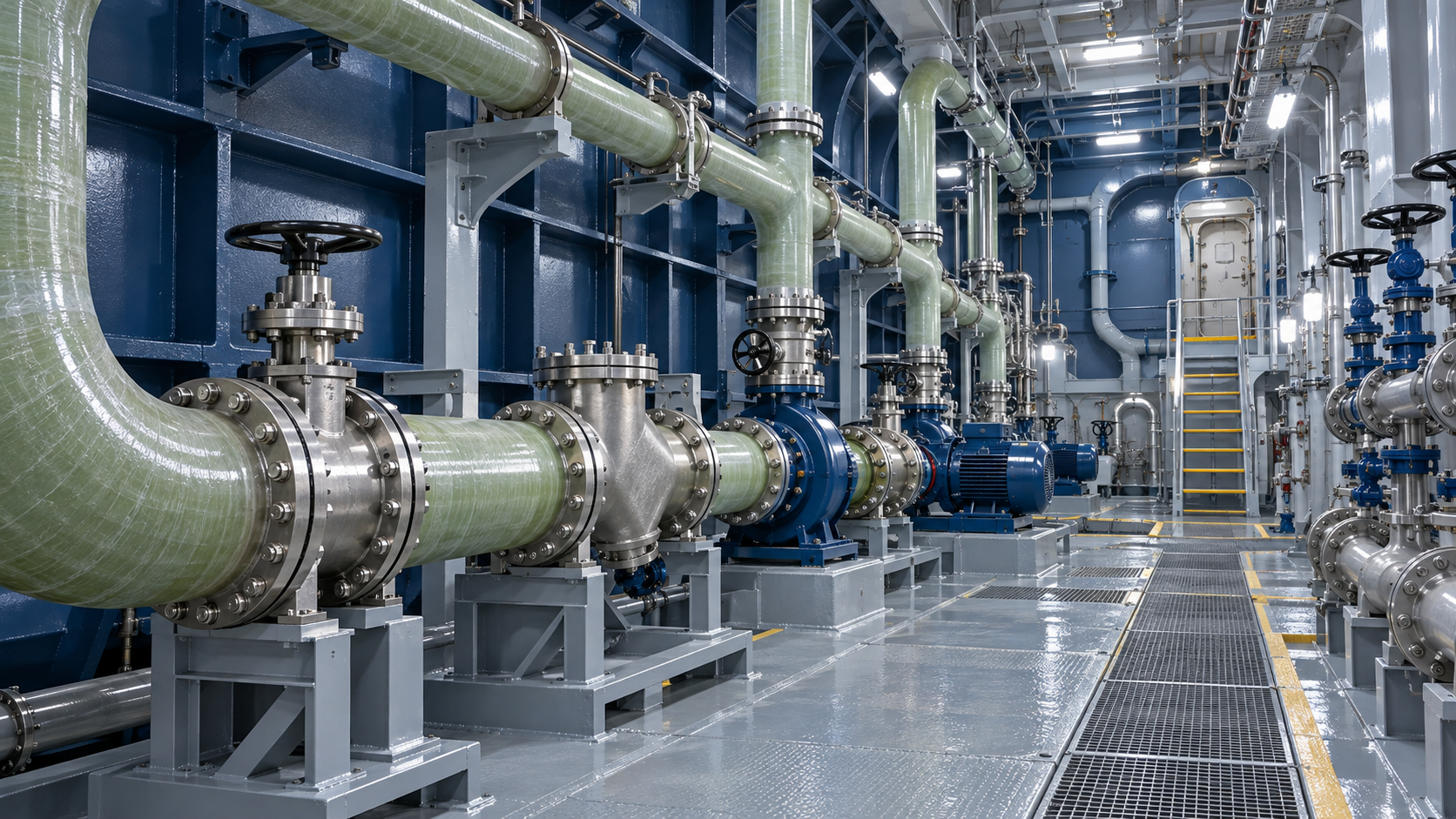
Glass-reinforced epoxy piping, for example, is attractive where seawater corrosion is the dominant concern and weight reduction is valuable. A qualified GRE Pipe for Marine & Offshore system may be considered for approved marine applications, particularly where corrosion-resistant non-metallic piping is permitted by the governing rules. That decision should not be based on corrosion resistance alone. The evaluator should review the system approval, permitted service category, pressure-temperature limits, fire performance provisions, joint design, support details, and any restrictions on use in machinery spaces, accommodation areas, or damage-prone locations.
Interfaces between different materials deserve close attention. A corrosion-resistant pipe section connected to unprotected steel valves, flanges, spool pieces, or supports can simply move the maintenance problem to the transition points. Dissimilar-metal joints may require electrical isolation or a defined bonding approach, depending on the materials and vessel corrosion-protection strategy. Composite pipe also needs properly designed clamps and saddles so that supports distribute load without crushing, abrading, or point-loading the pipe wall.
Places Where Corrosion Protection Commonly Fails
- Dead legs downstream of normally closed valves, where stagnant seawater remains for long periods.
- Low points without a practical drain or flushing arrangement.
- Valve chests, branch connections, and weld regions where coating application is difficult.
- Penetrations through bulkheads or decks where mechanical damage and crevice conditions can develop.
- Pipe supports that trap water against the external surface or damage protective coatings during vibration.
- Transitions between metallic and non-metallic piping where installation details do not account for differing stiffness or thermal movement.
These areas should be identified on the routing drawings before fabrication. A maintenance plan cannot fully compensate for a layout that deliberately creates inaccessible corrosion traps.
Hydraulic Performance Must Be Checked for the Operating Sequence
Ballast piping is not designed around one steady flow condition. A vessel may fill multiple tanks simultaneously, transfer water between tanks for trim or stability, discharge through pumps, strip residual water, and operate under heel or trim. The controlling hydraulic case may differ from the normal ballast rate. A line sized only for nominal pump capacity can perform poorly during stripping, in emergency transfer arrangements, or when several remote valves are positioned in a particular combination.
Pressure drop is driven by pipe diameter, route length, internal roughness, fittings, valves, strainers, branches, and flow velocity. Designers often focus on straight-pipe friction while underestimating local losses from valves and fittings. That is especially relevant in congested pump-room layouts, where short-radius bends, frequent direction changes, and compact valve manifolds can add substantial resistance.
Pipe diameter selection should start with required filling and deballasting time, available pump head, and permissible fluid velocity for the selected material and service. Higher velocity can reduce pipe size and initial weight, but may increase friction losses, noise, vibration, erosion at restrictions, and pressure surge severity. For composite piping, velocity limits should also be aligned with the pipe system supplier's approved service envelope and the class-approved design basis.
Stripping needs separate consideration. A main ballast pump may remove most of the water but leave residual volume due to tank geometry, line elevations, and entrained air. The stripping arrangement must account for suction lift, air ingress, drain paths, and the behavior of eductors or stripping pumps where used. A system that appears adequate on a simple flow diagram may fail to achieve effective stripping if the suction branch rises unnecessarily, a bellmouth is poorly located, or air pockets form at high points.
Air Management Is a Design Detail With System-Level Consequences
High points in ballast lines can trap air during filling and disrupt flow during discharge. Air accumulation can reduce effective capacity, cause intermittent pump suction, and increase the risk of pressure fluctuations. Venting arrangements should be positioned and sized for the actual geometry, including branches that may become isolated by valve operations. The same review should consider whether vents can permit unintended transfer, flooding, or contamination between tanks.
Pressure transients also matter. Rapid valve closure, pump starts and stops, and abrupt changes in flow direction can create surge loads above normal operating pressure. Long runs, high flow velocities, and quick-closing actuated valves increase the concern. A hydraulic transient assessment is appropriate when the system arrangement or operating sequence indicates meaningful surge risk. The resulting safeguards may include controlled valve closing times, pump control logic, relief provisions where permitted, stronger local pipe design, or changes to routing and diameter.
For Ship Ballast Piping, hydraulic design should be reviewed alongside the vessel's tank plan and operating philosophy. A well-sized main does not guarantee reliable operation if the valve arrangement makes it difficult to fill selected tanks independently, maintain segregation, or achieve the required sequence under damaged or partially unavailable conditions.
Class Rules Shape Both the Layout and the Evidence Package
Classification society requirements are not a final checklist applied after the piping design is complete. They influence material selection, routing, valve arrangements, penetrations, testing, and documentation from the early design stage. The applicable rules depend on the selected class society, vessel type, notation, piping location, and whether the line serves only ballast functions or interfaces with other systems.
Technical evaluators should avoid treating generic compliance statements as sufficient. The review should identify the exact rule set and approval basis that apply to the project. Requirements for a ballast line in a protected location may differ from those for a line passing through a machinery space, a collision-prone area, or a compartment where fire safety requirements are more demanding.
Several design subjects repeatedly require close review:
- Segregation and cross-connections: Ballast piping must not create an uncontrolled path between tanks, sea connections, bilge systems, fuel systems, cargo-related systems, or potable-water systems. Where cross-connections are permitted for defined operating purposes, the isolation arrangement must be clear, secure, and operable.
- Sea inlet and overboard protection: The arrangement of sea chests, suction valves, non-return devices, and overboard discharges must prevent unintended flooding while allowing inspection and maintenance.
- Remote valve operation: Valves needed for safe ballast operations may require remote actuation, local indication, or fail-safe behavior. The design review should include loss-of-power behavior and the accessibility of manual override.
- Bulkhead and deck penetrations: Penetrations may require approved seals, fire integrity measures, or structural protection. These details are particularly important for non-metallic pipes and mixed-material systems.
- Testing and inspection: Pressure testing, tightness testing, material traceability, joint qualification, and installation records are often part of the acceptance path. Documentation gaps can delay approval even when the installed system appears satisfactory.
Composite piping deserves an especially disciplined approval review. The pipe, fittings, adhesive or laminated joints, flange connections, supports, and installation procedure form one system. Substituting an unapproved fitting, using a different jointing process, or changing support spacing without engineering approval can invalidate assumptions behind the original certification.
Layout Choices Determine Whether Maintenance Remains Manageable
Ballast lines are commonly routed through confined spaces where structural members, cableways, ventilation ducts, and other piping compete for space. The pressure to simplify fabrication can lead to layouts that are difficult to inspect once the vessel is in service. For ballast duty, maintenance access should be treated as a functional requirement.
Isolation valves need clear operating access, readable identification, and room for overhaul where practical. Strainers require withdrawal space. Drains and vents should be operable without unsafe climbing or extensive removal of surrounding equipment. If pipe sections are expected to be renewed, the design should provide removable spools or sensible break points rather than forcing large-scale dismantling.
Support design also deserves more engineering attention than it usually receives. Supports must control vibration and accommodate vessel movement without imposing excessive load at flanges, valve bodies, or composite joints. The arrangement should allow expansion and contraction where temperature variation is relevant, while preventing line sagging that creates unintended low points. In areas exposed to impact, pipe guards or routing changes may be more reliable than assuming operators will avoid contact with the line.
A Practical Evaluation Sequence
When reviewing a ballast piping proposal, begin with the operating cases and then test whether the material, hydraulics, and approval basis support them. This order is more reliable than choosing a pipe type first and attempting to justify the system around it.
The strongest design packages make these answers visible in drawings, calculations, material specifications, and inspection records. A ballast system is easier to approve, operate, and maintain when those documents describe the same operating logic rather than presenting isolated engineering deliverables.
For technical evaluators, the most useful conclusion is straightforward: corrosion resistance, flow capacity, and class compliance cannot be assessed independently. The material may be suitable, the pump may have adequate head, and the drawings may show all required valves, yet the system can still underperform if its interfaces are poorly resolved. Reviewing those interfaces early is where ballast piping design delivers its greatest value.
Please give us a message
产品介绍产品介绍产品介绍产品介绍产品介绍产品介绍产品介绍产品介绍产品介绍产品介绍产品介绍产品介绍产品介绍产品介绍产品介绍产品介绍产品介绍产品介绍产品介绍产品介绍产品介绍产品介绍产品介绍产品介绍产品介绍产品介绍产品介绍产品介绍产品介绍产品介绍
Please give us a message
产品介绍产品介绍产品介绍产品介绍产品介绍产品介绍产品介绍产品介绍产品介绍产品介绍产品介绍产品介绍产品介绍产品介绍产品介绍产品介绍产品介绍产品介绍产品介绍产品介绍产品介绍产品介绍产品介绍产品介绍产品介绍产品介绍产品介绍产品介绍产品介绍产品介绍
Please give us a message
产品介绍产品介绍产品介绍产品介绍产品介绍产品介绍产品介绍产品介绍产品介绍产品介绍产品介绍产品介绍产品介绍产品介绍产品介绍产品介绍产品介绍产品介绍产品介绍产品介绍产品介绍产品介绍产品介绍产品介绍产品介绍产品介绍产品介绍产品介绍产品介绍产品介绍
Please give us a message
产品介绍产品介绍产品介绍产品介绍产品介绍产品介绍产品介绍产品介绍产品介绍产品介绍产品介绍产品介绍产品介绍产品介绍产品介绍产品介绍产品介绍产品介绍产品介绍产品介绍产品介绍产品介绍产品介绍产品介绍产品介绍产品介绍产品介绍产品介绍产品介绍产品介绍