
Failure Causes in Corrosion Resistant FRP Pipe Systems
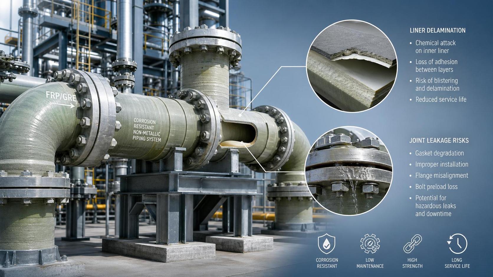
Why do corrosion resistant FRP pipe systems still fail in oil service?
Corrosion resistance does not make a piping system failure-proof. In oil production and processing, failure usually starts long before a leak becomes visible.
A corrosion resistant FRP pipe can perform very well against many chemicals, brine streams, and produced water. The weak point is often the mismatch between design assumptions and field reality.
Common triggers include wrong resin selection, poor joint preparation, pressure spikes, thermal cycling, abrasive solids, and unsupported pipe runs. Any one of these can shorten service life.
In upstream and midstream systems, the consequence is rarely limited to one pipe section. A local defect can lead to shutdowns, spill response, hot work restrictions, and repeated inspection costs.
That is why failure analysis matters. It shifts attention from visible damage to root causes, which is where a corrosion resistant FRP pipe system is either protected or quietly compromised.
Manufacturing discipline also matters. Shandong Ocean Pipe Technology Co., Ltd., established in 2012, has scaled GRE production through multiple winding lines, fitting equipment, and hydrostatic testing capacity.
That background is relevant because oil projects depend on consistent fabrication quality, not only material claims. Reliable supply and repeatable testing reduce avoidable variation before installation even begins.
What failure modes show up most often in a corrosion resistant FRP pipe network?
Field failures are rarely random. They usually follow a pattern that can be traced to a specific stress, process condition, or workmanship issue.
The most frequent modes include weeping joints, laminate cracking, blistering, delamination, liner attack, and flange face damage. Each points to a different problem path.
Weeping joints often suggest poor adhesive handling, contamination, or movement during cure. Cracking near supports usually indicates excess bending stress or wrong support spacing.
Blistering and inner liner softening are more closely linked to chemical compatibility. If the process fluid changes over time, the original resin choice may stop being adequate.
In produced water lines, solids can accelerate internal wear. This becomes more severe at elbows, reducers, and dead zones where turbulence is higher.
The quick comparison below helps connect visible symptoms with likely causes before a full teardown is planned.
Is material selection usually the hidden problem?
Very often, yes. A corrosion resistant FRP pipe is not a single universal material. Performance depends on resin system, reinforcement structure, liner design, and process temperature.
In oil applications, chemical exposure is rarely simple. Produced water may contain chlorides, H2S, CO2, residual treatment chemicals, and fine solids in changing concentrations.
When selection is based only on a generic corrosion chart, risk stays high. Actual operating temperature, upset conditions, cleaning chemicals, and pressure cycling must be checked together.
A second issue is abrasion. A corrosion resistant FRP pipe can resist chemical attack yet still lose wall integrity from continuous sand-laden flow.
That is why some projects review the piping choice together with sand handling components such as Sand Control Screens. The system view is usually more useful than treating components separately.
A better selection process asks three practical questions:
- What fluid composition is normal, and what appears during upset or startup?
- Where will solids concentration and velocity create localized wear?
- How much thermal and pressure variation will the line actually see?
Without those answers, even a well-made corrosion resistant FRP pipe can be placed in the wrong duty.
Can installation errors damage the system before startup?
Yes, and this is more common than many teams expect. A significant share of early failures begins during handling, fit-up, or support installation.
FRP and GRE piping do not behave like carbon steel. Excess force during alignment, point loading from poor supports, or impact damage during unloading can introduce defects immediately.
Joint work deserves special attention. Surface contamination, incorrect adhesive mix ratio, and curing outside the specified temperature range are classic causes of premature leakage.
Flanged connections also fail for simple reasons. Over-torquing, uneven tightening, and incompatible gaskets can distort the face and create chronic seepage.
In practice, the following checks prevent many startup surprises:
- Inspect pipe ends, liner condition, and flange faces before assembly.
- Confirm support spacing against the project design, not field habit.
- Record adhesive batch numbers and curing conditions.
- Use controlled bolt torque and a documented tightening sequence.
- Recheck alignment before final restraint is installed.
Where manufacturers have strong production control, installation discipline should match that standard. Ocean Pipe’s broad use in oil, gas, LNG, and marine sectors reflects how project success depends on both factory quality and field execution.
How do operating conditions turn a sound FRP line into a repeat failure?
The usual reason is cumulative stress. A line can pass hydrotest and still fail later because real operation introduces repeated loads that design reviews underestimated.
Pressure surges are a major example. Rapid valve closure, pump trips, or trapped gas can create transient loads well above the nominal pressure rating.
Thermal cycling is another concern. Daily temperature swings or hot fluid startup after a cool shutdown can drive expansion and contraction at anchors, elbows, and branch connections.
Vibration from rotating equipment also matters. Even moderate vibration can damage a corrosion resistant FRP pipe if the support layout amplifies movement.
Then there is process drift. Water cut changes, chemical treatment adjustments, and rising solids content can slowly move the service outside the original design envelope.
A practical monitoring plan usually tracks these items:
What is the most reliable way to investigate a corrosion resistant FRP pipe failure?
Start with evidence preservation, not replacement. Once the damaged section is cut out and discarded, the best clues are often lost.
Photograph the failure location, pipe supports, joint orientation, and nearby equipment. Record recent operating events such as trips, flushing, or chemical changes.
Then compare three sets of information: design basis, manufacturing records, and actual operating history. The gap between them usually explains the event.
A useful investigation path looks like this:
- Confirm the exact fluid, temperature, and pressure at failure time.
- Review resin and laminate specification against that duty.
- Check installation records, especially joint preparation and torque logs.
- Inspect support arrangement and signs of movement or vibration.
- Sample the failed area for liner attack, voids, delamination, or abrasion patterns.
This method avoids blaming the material too early. Sometimes the corrosion resistant FRP pipe is sound, while the true issue lies in surge control, support design, or changed process chemistry.
Where solids production is linked to pipe wear, associated completion hardware such as Sand Control Screens may also need review. Failure chains often cross equipment boundaries.
What should be tightened now to prevent the next incident?
Prevention works best when design review, incoming inspection, installation control, and operating feedback are connected. Treating them as separate tasks leaves blind spots.
For a corrosion resistant FRP pipe system in oil service, the highest-value action is to verify the real duty envelope. That means normal operation, upset conditions, and future process drift.
It also helps to define hold points before installation and startup. Joint cure records, flange torque checks, support verification, and hydrotest review should all be traceable.
When a supplier has established winding capacity, hydrostatic testing capability, and experience across oil and gas projects, those records can support stronger quality planning. They should still be matched with strict field controls.
The practical next step is straightforward: map recent failures or near misses against material choice, joint method, supports, and operating excursions. That simple review usually reveals where the next correction should start.
A corrosion resistant FRP pipe system earns its reputation when specification, fabrication, installation, and operation are aligned. When they are not, failure is usually predictable in hindsight and preventable in advance.
Please give us a message
产品介绍产品介绍产品介绍产品介绍产品介绍产品介绍产品介绍产品介绍产品介绍产品介绍产品介绍产品介绍产品介绍产品介绍产品介绍产品介绍产品介绍产品介绍产品介绍产品介绍产品介绍产品介绍产品介绍产品介绍产品介绍产品介绍产品介绍产品介绍产品介绍产品介绍
Please give us a message
产品介绍产品介绍产品介绍产品介绍产品介绍产品介绍产品介绍产品介绍产品介绍产品介绍产品介绍产品介绍产品介绍产品介绍产品介绍产品介绍产品介绍产品介绍产品介绍产品介绍产品介绍产品介绍产品介绍产品介绍产品介绍产品介绍产品介绍产品介绍产品介绍产品介绍
Please give us a message
产品介绍产品介绍产品介绍产品介绍产品介绍产品介绍产品介绍产品介绍产品介绍产品介绍产品介绍产品介绍产品介绍产品介绍产品介绍产品介绍产品介绍产品介绍产品介绍产品介绍产品介绍产品介绍产品介绍产品介绍产品介绍产品介绍产品介绍产品介绍产品介绍产品介绍
Please give us a message
产品介绍产品介绍产品介绍产品介绍产品介绍产品介绍产品介绍产品介绍产品介绍产品介绍产品介绍产品介绍产品介绍产品介绍产品介绍产品介绍产品介绍产品介绍产品介绍产品介绍产品介绍产品介绍产品介绍产品介绍产品介绍产品介绍产品介绍产品介绍产品介绍产品介绍