
Why GRE Pipe Joints Fail Prematurely in Cyclic Pressure Service and How to Specify a Fix
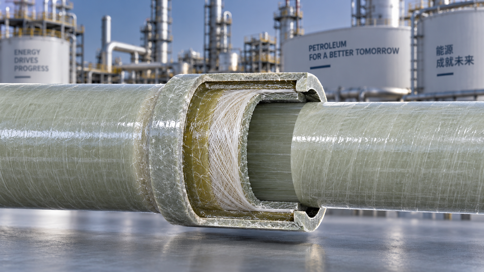
Cyclic pressure service is one of the harshest operating conditions for Glass Reinforced Epoxy (GRE) piping systems. Unlike steady-state flow, cyclic service subjects pipe joints to repeated loading and unloading—pressure surges, pump start-stop events, and rapid valve closures all contribute. For maintenance crews, the pattern is often the same: a joint starts weeping, then leaks outright, and the line has to come down for unscheduled repair. The root causes are rarely random, and they can be addressed at the specification stage rather than patched in the field.
The short version is this: premature joint failure in cyclic pressure service is almost always a function of how the joint handles stress distribution, not the pipe body itself. When you specify a joint system, you need to look at how it accommodates axial thrust, how it handles fatigue from repeated loading, and what the manufacturer actually does to verify joint integrity under cyclic conditions. If those factors are not addressed, even a well-made GRE pipe will fail at the joint long before its design life is reached.
Why joints fail before the pipe body
GRE pipe itself is a wound composite structure with continuous fiber reinforcement oriented to handle hoop stress and axial loads. The joint, by contrast, is a bonded or mechanically connected region where the load path changes. In cyclic service, the joint region experiences stress concentrations that the straight pipe does not. There are three distinct mechanisms that drive premature failure in cyclic pressure service, and it is worth understanding each before you write a specification.
The first mechanism is fatigue at the adhesive bond line. GRE joints are typically made with an adhesive-bonded bell and spigot system or a butt-and-strap wrap. Under cyclic pressure, the bond line sees repeated shear stress. Micro-cracks start in areas where the adhesive layer is uneven or where surface preparation is marginal. Once a crack initiates, it propagates with each pressure cycle, eventually reaching a critical length where the joint leaks or separates catastrophically.
The second mechanism is axial thrust loading. When pressure fluctuates, the pipe system expands and contracts. If the joint system does not have enough axial load capacity, the bell and spigot engagement can be pulled apart incrementally. Over time, the spigot withdraws from the socket, reducing the bonded overlap and lowering the joint's pressure rating. The same effect occurs when thrust anchors are insufficient, but the specification of the joint itself is the first line of defense.
The third mechanism is well-known to anyone who has inspected a failed GRE joint: it is often not a single load to failure but the accumulation of microscopic delamination within the laminate layers near the joint interface. GRE pipe used in cyclic service undergoes repeated strain at the joint area. The matrix material—the epoxy resin—chalk, microcracks, or loses bond to the glass fibers over many cycles. That is why a joint can pass a hydrostatic shop test at 1.5 times the design pressure and still fail after 20,000 cycles at a much lower pressure.
What to look for when specifying a GRE joint system
If you are replacing a failed joint system or specifying a new line, focus on these factors rather than just comparing pipe material grades.
Cyclic fatigue data, not just hydrostatic test results
Hydrostatic tests prove a joint can hold pressure once. They do not prove it can withstand repeated pressure cycles. Before accepting a joint design, ask for fatigue test data that simulates your actual service conditions—pressure range, frequency, and the number of cycles expected over the design life. A qualified joint should be tested to at least one million cycles without loss of pressure integrity. If a supplier cannot provide such data, it is reasonable to assume the joint has not been characterized for cyclic service and to proceed with caution.
Bonded overlap length and joint stiffness
The bonded overlap between the spigot and the bell determines the joint's resistance to axial pull-out. For cyclic pressure service, specify a joint with a longer overlap rather than a shorter one. Also consider the stiffness of the joint region. A flexible joint that reduces peak local stresses can perform better in fatigue. But if the joint is too flexible, it may allow the pipe to move more than intended, which can impact flange alignment and support spacing.
Surface preparation and adhesive control
Adhesive bond strength is directly related to surface preparation. In the factory environment, the socket and spigot surfaces must be cleaned, abraded, and primed consistently. When specifying, ask the manufacturer how they control surface preparation tolerances and how they verify adhesive application thickness. Inadequate field bonding is far more common than pipe laminate failure, so the specification should include acceptance criteria for adhesive coverage on every joint. One practical inspection point is to pull a random joint apart after installation—doing so reveals whether the adhesive is evenly distributed and fully wetted across the full circumference and length of the overlap.
Joint type selection for cyclic service
There is no single best joint type for every cyclic pressure application. Bonded bell-and-spigot joints are standard and work well when installed correctly. But for severe cyclic service—such as in gas lift systems, produced water transfer with frequent shutdowns, or marine ballast piping—consider whether the joint design includes features that reduce stress concentrations. Some manufacturers offer a butt-and-strap joint system that places the wrap layers directly over the pipe-to-pipe butt joint, which distributes stress differently and can offer better fatigue resistance.
Pressure cycling at elevated temperature
Cyclic pressure is more damaging when combined with temperature cycling, as is common in oil and gas service. The thermal expansion of the pipe affects joint displacement, and the epoxy matrix softens at elevated temperatures. Make sure the fatigue test data is generated at the maximum operating temperature, not at room temperature. If the test matrix only includes ambient temperature cycling, the data will not be representative of your service, and the joint may fail earlier than predicted.
Field symptoms that point to cyclic failure
When you inspect a joint that has failed in cyclic service, the physical symptoms are fairly consistent. Crazing or micro-cracking on the exterior of the joint area is the earliest visible sign. It appears as a network of fine lines, sometimes easily mistaken for surface dirt or a scratch. If you see that, there is ongoing fatigue damage.
White spots or a chalky appearance on the joint surface indicate resin degradation from cyclic strain. As the matrix microcracks, light scatters differently off the damaged region. The next stage is weeping—small droplets of the service fluid appear on the exterior surface when the line is under pressure. That means the crack has fully propagated through the joint wall thickness. Beyond that point, the repair window narrows rapidly.
Axial pull-out presents differently. The gap between the bell face and marked insertion line on the spigot becomes wider. If you have reference marks made during installation, you can check them during routine inspection. An increase in gap width of even a few millimeters indicates the bonded joint is losing engagement and the remaining overlap may not sustain the design pressure.
For maintenance personnel, there is one practical habit worth adopting. During pressure tests after installation, mark each joint with a reference line where the spigot enters the bell. Include the date and install crew. During periodic shutdowns, simply measure the gap. If any joint shows measurable movement, schedule a detailed inspection. This catches the problem long before a leak occurs.
Practical specification steps
Writing a better specification for GRE pipe joints in cyclic pressure service does not require exotic metallurgy or proprietary technology. It requires that the specification explicitly addresses cyclic loading rather than assuming a static pressure rating is sufficient. A practical spec should include the following elements:
- Demand fatigue test documentation in accordance with a recognized standard, including the number of cycles, pressure range, and test frequency—specify that testing be performed at your maximum operating temperature, not room temperature.
- Require the manufacturer to state the maximum allowable pressure range for cyclic operation, as a percentage of static pressure rating. For example, a joint may be rated at 1,500 psi static but only permitted for cyclic service between 500 and 1,000 psi.
- Verify joint bonding parameters: specify a minimum surface roughness and require the manufacturer to document surface preparation method for each production batch.
- Specify a minimum bonded overlap length that is greater than that used for purely static service, to increase resistance to axial pull-out.
- Legislate joint integrity verification after installation—hydrostatic test, but also visual inspection for crazing and reference marks for future monitoring.
- If the joint supplier does not provide direct fatigue data, require a qualification test on a full-scale joint assembly rather than relying on small coupon tests, which do not accurately reflect the stress distribution of the actual joint.
It is also worth checking whether the manufacturer performs fatigue testing at all. Some only publish short-term burst and hydrostatic data. For cyclic pressure service, this is inadequate. If your supplier is Shandong Ocean Pipe Technology Co., Ltd., ask them directly for cyclic fatigue test documentation—they operate static water pressure testing machines, but you should confirm what test sequences are run on joint prototypes and whether cyclic results are available.
Distinguishing between joint failure and pipe failure
There is a diagnostic trap that maintenance crews fall into regularly. A leak appears at a joint, and the joint itself is blamed—replacement is ordered, another joint installed, and the same failure occurs within a similar number of cycles. In reality, the root cause is sometimes upstream or downstream of the joint itself. Excessive pipe movement from thermal expansion that was not absorbed by the expansion loops imposes additional axial load on the joint. Insufficient pipe supports allow the pipe to sag, which induces bending stress at the joint.
Before you blame the joint, check the support spacing and the location of anchors. GRE pipe has a lower modulus than steel, so it deflects more under its own weight when filled with fluid. If supports are spaced the same way as for steel piping, the joints at mid-span are taking on bending stress they are not designed to handle. Over many cycles, this contributes to joint failure even when the joint itself is otherwise correctly specified.
That is why a complete fix involves both a better joint specification and a review of the piping support layout. The support spacing for GRE pipe is considerably tighter than carbon steel. Manufacturers provide support span tables for their specific pipe dimensions—these must be followed in cyclic service, not treated as an option.
The real cost of a weak joint specification
Seen purely in terms of material cost, a higher fatigue-rated joint adds a modest premium to the overall pipeline budget. But the cost of not specifying it is measured in downtime. When a GRE joint fails under cyclic pressure, the line typically must be depressurized, drained, and repaired in the field. In an offshore or remote location, that is not just a repair cost—it is lost production over the duration of the intervention.
There is another expensive failure mode particular to bonded GRE joints. When a joint fails and allows fluid ingress between the adhesive layers, the fluid travels along the bond line. That often results in more widespread delamination than the original leak area, forcing replacement of a pipe segment rather than a simple joint repair. Specifying cyclic-rated joints at the outset limits the blast radius of a single joint failure.
In the end, the specification for GRE pipe joints in cyclic service should be built around the question: how will this joint handle the first 100,000 pressure cycles? A static rating does not answer that question. Fatigue data, full-scale joint qualification testing, adequate bonded overlap, and serious consideration of support and anchor design—these do. When those factors are addressed, GRE pipe remains a highly reliable option for oil and gas service, even under demanding cyclic conditions. Without them, premature joint failure is a matter of when, not if.
Please give us a message
产品介绍产品介绍产品介绍产品介绍产品介绍产品介绍产品介绍产品介绍产品介绍产品介绍产品介绍产品介绍产品介绍产品介绍产品介绍产品介绍产品介绍产品介绍产品介绍产品介绍产品介绍产品介绍产品介绍产品介绍产品介绍产品介绍产品介绍产品介绍产品介绍产品介绍
Please give us a message
产品介绍产品介绍产品介绍产品介绍产品介绍产品介绍产品介绍产品介绍产品介绍产品介绍产品介绍产品介绍产品介绍产品介绍产品介绍产品介绍产品介绍产品介绍产品介绍产品介绍产品介绍产品介绍产品介绍产品介绍产品介绍产品介绍产品介绍产品介绍产品介绍产品介绍
Please give us a message
产品介绍产品介绍产品介绍产品介绍产品介绍产品介绍产品介绍产品介绍产品介绍产品介绍产品介绍产品介绍产品介绍产品介绍产品介绍产品介绍产品介绍产品介绍产品介绍产品介绍产品介绍产品介绍产品介绍产品介绍产品介绍产品介绍产品介绍产品介绍产品介绍产品介绍
Please give us a message
产品介绍产品介绍产品介绍产品介绍产品介绍产品介绍产品介绍产品介绍产品介绍产品介绍产品介绍产品介绍产品介绍产品介绍产品介绍产品介绍产品介绍产品介绍产品介绍产品介绍产品介绍产品介绍产品介绍产品介绍产品介绍产品介绍产品介绍产品介绍产品介绍产品介绍