
Connecting FRP Pipe to Existing Steel Pipelines in Refinery Retrofit Projects: Isolation and Flange Details
Connecting FRP Pipe to Existing Steel Pipelines in Refinery Retrofit Projects: Isolation and Flange Details
Refinery retrofit managers face a critical engineering challenge when integrating FRP piping into legacy steel networks: ensuring leak-free, corrosion-resistant joints without shutting down production. This article addresses the isolation requirements, flange compatibility, and installation practices that determine whether your connection succeeds or becomes a maintenance liability. Based on field experience with GRE pipe systems across CNOOC, Sinopec, and international refinery projects, we provide actionable specifications for project leaders evaluating FRP-to-steel connections.
Why Standard Flange Connections Fail Between FRP and Steel in Refinery Service
Direct bolting of FRP flanges to steel counterparts creates hidden failures that surface within 6-18 months of service. The root cause is differential thermal expansion—steel expands at roughly 11.7×10⁻⁶/°C, while glass-reinforced epoxy pipe expands only 9-11×10⁻⁶/°C. In refinery environments where process temperatures fluctuate between ambient and 90°C+, this mismatch concentrates stress at the bolted joint.
Project managers often overlook another critical factor: cathodic isolation. When FRP pipe connects directly to carbon steel in refinery service, galvanic corrosion accelerates at the interface, particularly where moisture and chloride-laden process fluids are present. Unlike all-steel systems, FRP does not conduct electrical current, which disrupts existing cathodic protection systems designed for continuous metallic pipelines.
The third failure mechanism relates to flange face finish. Steel pipe flanges in existing refineries typically have a serrated finish per ASME B16.5, but FRP flanges require smoother, gasket-compatible surfaces. Mating these mismatched faces without proper isolation causes gasket extrusion and premature leakage, especially under thermal cycling conditions common in refinery throughput changes.
Critical Isolation Requirements When Connecting FRP to Existing Steel Pipelines
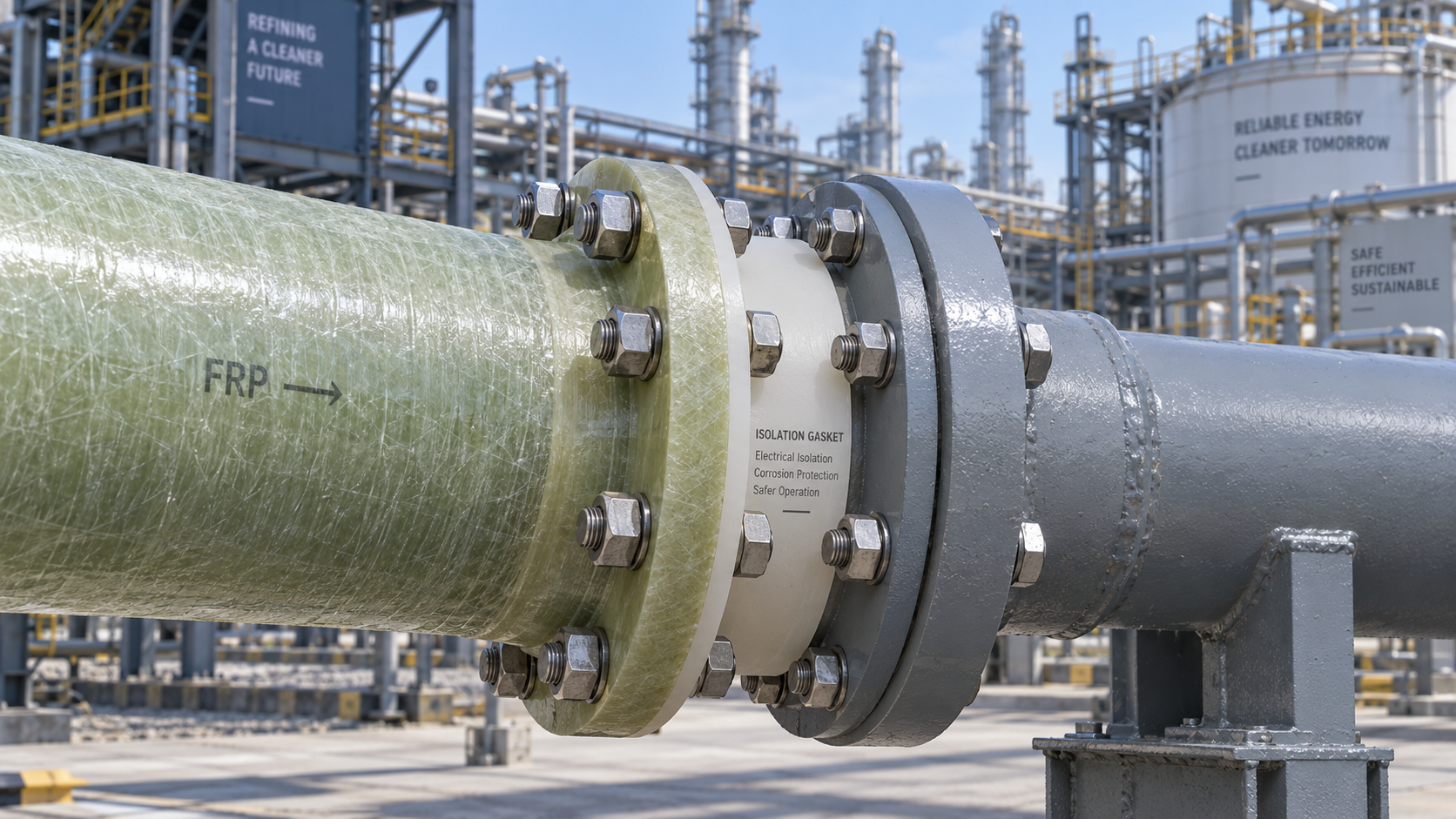
Isolation begins with a clear specification for dielectric isolation kits. These kits—comprising insulating gaskets, isolating sleeves, and washers—must be rated for the full operating pressure and temperature of your refinery service. Standard kits use G10 phenolic laminate or PTFE-faced materials for the isolating gasket, with stainless steel sleeves covering all bolt shanks to prevent metal-to-metal contact.
For refinery retrofits handling hydrocarbons, your isolation specification should mandate a fire-safe design. This means selecting non-combustible isolating materials that maintain sealing integrity even when exposed to pool fire temperatures exceeding 700°C for 30 minutes. Many standard isolation kits fail this requirement, creating a risk that regulatory inspectors will flag during turnaround audits.
Location of isolation points matters as much as the kit specification. Place isolation flanges at every FRP-to-steel transition, plus at tie-in points where grounding straps may otherwise create unintended electrical continuity. For long FRP runs connected to steel at both ends, double isolation is required—otherwise, the FRP section becomes a capacitor storing static charge from flowing hydrocarbons, posing ignition risk.
Bonding and grounding procedures must be documented in your project's installation method statement. Each isolating flange requires a visible, labeled bonding stud for temporary grounding during installation and maintenance. The project engineer should verify with a multimeter that resistance across the isolation point exceeds 25 megaohms before hydrotest and again before commissioning.
Selecting the Right Flange Standard and Facing for FRP-to-Steel Retrofits
Do not default to ASME B16.5 dimensions for FRP flanges, despite their visual similarity. FRP pipe flanges are typically manufactured to ASME B16.5 bolt patterns for interchangeability, but face thickness follows different rules due to creep-rupture behavior of the composite material. Specify flanges with a minimum face thickness of 40-50% greater than steel equivalents for the same pressure class in refinery service.
Flange facing selection directly impacts gasket performance. The recommended face finish for FRP flanges is 125-250 microinch Ra with a concentric spiral groove, not the 32-125 microinch serrated finish used for steel. If your existing steel pipeline has serrated flanges, install full-face gaskets of a resilient material like compressed non-asbestos fiber (CNAF) with a PTFE envelope to accommodate the roughness mismatch.
For high-pressure refinery applications above ANSI 300# rating, consider using a raised-face FRP flange with a custom trapezoidal ring groove. This design traps the gasket more effectively under thermal cycling and vibration. However, conduction of this groove requires precision machining—confirm your FRP manufacturer has CNC capability for this work, as many lower-cost shops cannot hold the required tolerances.
Flange Bolt Torque and Compression Limits: Industry Data You Need
FRP flanges cannot tolerate the bolt loads applied to steel flanges. While a 4-inch ANSI 150 steel flange might require 80-105 ft-lbs of torque, the same FRP flange typically needs only 35-45 ft-lbs. Exceeding this range crushes the composite face—damage that is invisible immediately but causes leakage after thermal cycling exposes the compression set.
Project leaders should specify lubrication and torque procedure in the installation package. Apply molybdenum disulfide grease to bolts and nuts, but never to the gasket area. Tighten bolts in a star pattern, achieving 30% of final torque on the first pass, 70% on the second, and 100% on the third pass. Allow 30 minutes after final tightening to re-torque, accounting for stress relaxation inherent in composite materials.
Consider gasket stress relaxation data from your gasket manufacturer. For refinery hydrocarbon service with FRP flanges, a gasket seating stress target of 1,500-2,500 psi is appropriate—well below typical steel flange seating stress of 4,000-6,000 psi. This lower value accommodates the limited bolt load FRP can accept while maintaining a positive seal under 90°C operating temperatures.
Field Joint Design Options: Mechanical Couplings vs. Flanged Connections
While flanged connections are the most straightforward for retrofit tie-ins, mechanical couplings offer specific advantages when space constraints or alignment issues exist at existing steel pipe terminations. A high-performance bolted mechanical coupling, designed for FRP-to-steel connectivity and rated for refinery service, eliminates the need for mating flange faces while providing both pressure containment and electrical isolation.
The coupling approach requires careful assessment of pipe end tolerances. Steel pipe ends in existing refinery service may be oval or have surface scale that prevents an adequate seal seat. For such cases, a flanged connection provides greater tolerance for minor misalignment and easier inspection capability. Budget for wrapper-type corrosion protection at mechanical coupling ends if they are buried or in enclosed trenches.
For high-vibration zones such as pump suction or discharge lines, flanged connections outperform couplings due to their higher bending moment capacity. However, if the existing steel line has limited support spacing, the heavier FRP flange adds dead weight—verify support spacing against the FRP pipe manufacturer's maximum span table before finalizing the connection method.
Installation Sequencing and Hydrotest Considerations for Retrofit Tie-ins
Proper installation sequencing prevents structural damage to FRP during the retrofit tie-in. First, install and align the steel-side flange, ensuring no residual piping strain at the connection point. Then, attach the FRP flange with the isolation kit, but leave the final bolt torque for after thermal equalization has occurred over 24 hours.
Hydrotest pressures must account for FRP's lower short-term burst rating versus steel. Test the new FRP section separately at 1.5 times its design pressure, not the steel pipeline's hydrotest pressure. If integrated testing is unavoidable, install a blind flange at the FRP section boundary and test each system to its own specification—testing FRP to steel code pressures may cause irreversible damage.
During hydrotest, monitor the isolation flange for signs of water intrusion at the gasket face. Use dry indicating chalk around the flange periphery before pressurization; any discoloration indicates a leak path requiring re-torque or gasket replacement. Document torque values, gasket type, and isolation kit serial numbers in the permanent dossier for future turnaround planning.
Quality Verification and Inspection Checklists for Project Managers
Before accepting the FRP-to-steel connection, verify that the isolation kit matches the purchase specification. Check certificate documentation confirming dielectric rating, fire-safety classification, and chemical compatibility with the process fluid. Many project failures trace back to substitution of a cheaper isolation kit at site level—audit this requirement rigorously.
Conduct a post-installation electrical continuity test across each isolation joint. For refinery retrofits where existing cathodic protection is in service, confirm the FRP section has not created an unintended grounding path. Compare readings against the pre-installation baseline and record them in the handover documentation.
Verify flange alignment within the manufacturer's tolerance—typically 1.5mm offset maximum for 150# class flanges. Thermal cycling over the first year is the ultimate test; schedule an infrared inspection at the six-month operating mark to detect any abnormal heat signatures indicating restricted flow or friction at the joint area.
Maintenance Planning and Long-Term Integrity Monitoring
Include the FRP-to-steel connections in your refinery's corrosion monitoring database with a distinct equipment type code. These joints represent hybrid locations that are neither fully metallic nor fully composite in behavior—maintenance personnel need specific training to inspect them correctly without damaging the isolating components.
Plan a bolted joint re-torque at the first planned turnaround following installation. FRP exhibits viscoelastic behavior; after 12-24 months of service at temperature, initial bolt load will have decayed by 15-25%. One-time re-torque to the original specification restores reliable performance. Subsequent re-torque is generally not required if initial installation used proper stress relaxation allowances.
Stock spare isolation kits and gaskets for each connection size to minimize unplanned downtime. Given the manufacturing lead time for custom FRP flanges—often 8-12 weeks—maintaining spares of the isolating components is more effective than stocking the complete flange assembly. Verify spare part compatibility during the design phase to ensure interchangeable dimensions.
Retrofit projects in operating refineries succeed when project leaders understand that FRP-to-steel connections demand engineered isolation, matched flange design, and deliberate installation procedures. By specifying dielectric isolation with fire-safe materials, selecting flange faces that accommodate composite properties, and following torque protocols developed specifically for FRP, you eliminate the three most common failure modes. The resulting system leverages FRP's corrosion resistance for 30+ years of service while maintaining safe interconnection with legacy steel infrastructure. Schedule a technical review with your FRP manufacturer early—discuss your flange ratings, process temperatures, and isolation requirements to confirm these engineering parameters match their product certification limits before issuing the purchase order.
Related Posts
- ▶ Connecting FRP Pipe to Existing Steel Pipelines in Refinery Retrofit Projects: Isolation and Flange Details
- ▶ Why FRP Pipe Delamination Occurs in High-Temperature Oil Emulsion Service and How to Prevent It
- ▶ FRP vs. Carbon Steel for Sour Gas Gathering Lines: A Lifecycle Cost Comparison from Field Data
Please give us a message
产品介绍产品介绍产品介绍产品介绍产品介绍产品介绍产品介绍产品介绍产品介绍产品介绍产品介绍产品介绍产品介绍产品介绍产品介绍产品介绍产品介绍产品介绍产品介绍产品介绍产品介绍产品介绍产品介绍产品介绍产品介绍产品介绍产品介绍产品介绍产品介绍产品介绍
Please give us a message
产品介绍产品介绍产品介绍产品介绍产品介绍产品介绍产品介绍产品介绍产品介绍产品介绍产品介绍产品介绍产品介绍产品介绍产品介绍产品介绍产品介绍产品介绍产品介绍产品介绍产品介绍产品介绍产品介绍产品介绍产品介绍产品介绍产品介绍产品介绍产品介绍产品介绍
Please give us a message
产品介绍产品介绍产品介绍产品介绍产品介绍产品介绍产品介绍产品介绍产品介绍产品介绍产品介绍产品介绍产品介绍产品介绍产品介绍产品介绍产品介绍产品介绍产品介绍产品介绍产品介绍产品介绍产品介绍产品介绍产品介绍产品介绍产品介绍产品介绍产品介绍产品介绍
Please give us a message
产品介绍产品介绍产品介绍产品介绍产品介绍产品介绍产品介绍产品介绍产品介绍产品介绍产品介绍产品介绍产品介绍产品介绍产品介绍产品介绍产品介绍产品介绍产品介绍产品介绍产品介绍产品介绍产品介绍产品介绍产品介绍产品介绍产品介绍产品介绍产品介绍产品介绍